Camera Connection Using V4L2

Hello,
We are trying to receive camera video through MIPI. We are in the process of developing a camera driver, but we haven’t been able to find any examples of video capture using V4L2.

It seems that CAMSS uses V4L2 (i.e., the Linux upstream framework), but in our kernel, a downstream driver named camera (this is the actual name of the driver) is already loaded.

Are there any example applications that receive video using V4L2? Also, which image sensor is used in those examples?

Another question we have is about the two MIPI video transmission modes: continuous mode and non-continuous mode.
Does Rubik PI support continuous mode?

continuous mode and non-continuous mode,both modes are supported.

“I want to receive camera video using v4l2. What are the sensor driver source code and device tree that I need to reference? Also, the current camera structure is based on Qualcomm’s downstream kernel. How should I change this to the upstream kernel?”

Let me know if you’d like further clarification or help with the technical details!

Using a V4L2 application to capture raw frame data
How to capture raw frame data using an application that supports the V4L2 interface.
Enable CamSS driver

  1. Download upstream kernel source code using the following command.
    devtool modify linux-qcom-custom
    This downloads the kernel source code to the following location.
    /build-qcom-wayland/workspace/sources/linux-qcom-custom/
  2. Apply the following change to enable the CamSS driver in the device tree:
    /build-qcom-wayland/workspace/sources/linux-qcom-custom/arch/
    arm64/boot/dts/qcom/qcs6490-rb3gen2.dts
    &camss {
    -status = “disabled”;
    +status = “okay”;
    ports {
    #address-cells = <1>;
    #size-cells = <0>;
  3. Build the image following the Yocto build instructions in Build Guide.
  4. Flash the image following the instructions in Flash Images.

Build and push the media controller utility and Yavta application
1 . Build Yavta and the media controller.
bitbake yavta
2. Push the binaries to the device. In the following example, is the directory of the Qualcomm software release.
NOTE Connect to the device console using SSH. See How To SSH? for instructions.
scp /build-qcom-wayland/tmp-glibc/deploy/ipk/armv8-2a/v4l-
utils_1.22.1-r0_armv8-2a.ipk root@[ip-addr]:/var/cache/camera/
scp /build-qcom-wayland/tmp-glibc/deploy/ipk/armv8-2a/yavta_0.0-
r2_armv8-2a.ipk root@[ip-addr]:/var/cache/camera/
scp /build-qcom-wayland/tmp-glibc/deploy/ipk/armv8-2a/media-
ctl_1.22.1-r0_armv8-2a.ipk root@[ip-addr]:/var/cache/camera/
scp /build-qcom-wayland/tmp-glibc/deploy/ipk/armv8-2a
\libv4l_1.22.1-r0_armv8-2a.ipk root@[ip-addr]:/var/cache/camera/
3. Create a shell connection to the device:
ssh root@[ip-addr]
4. Disable the camera module.
The camera module cannot coexist with the CamSS driver.

Move the camera.ko module out from/lib/modules/* to make it not load automatically,
then reboot the device.
#mount -o rw,remount /
#mv /lib/modules//updates/camera.ko /*
5. Install the media-ctl, libv4l, v4l-utils, and yavta packages.
#opkg --nodeps install /var/cache/camera/media-ctl_1.22.1-r0_armv8-2a.ipk
–force-reinstall
#opkg --nodeps install /var/cache/camera/libv4l_1.22.1-r0_armv8-2a.ipk –
force-reinstall
*#opkg --nodeps install /var/cache/camera/v4l-utils_1.22.1-r0_armv8-2a.ipk *
–force-reinstall
#opkg --nodeps install /var/cache/camera/yavta_0.0-r2_armv8-2a.ipk –
force-reinstall
6. Optionally, add the sensor driver and CamSS modules.
#modprobe imx412
#modprobe qcom-camss

This is an optional step since the imx412 and qcom-camss modules in /lib/modules are loaded
automatically. Modprobe is used to add/remove modules from the Linux Kernel. The imx412 and
qcom-camss modules are located in the following paths on the device:
□ /lib/modules//kernel/drivers/media/i2c/imx412.ko
□ /lib/modules/
/kernel/drivers/media/platform/qcom/camss/qcom-camss.ko
Loading of the qcom_camss and imx412 modules can be verified with the following lsmod
command:
#lsmod | grep qcom_camss
#lsmod | grep imx412

Check the media node number
Run the following command to print the media device node number for the CamSS driver.
If /dev/media0 does not list the qcom-camss driver, try with /dev/media1.
#media-ctl -p -d /dev/media0 | grep camss
图片

Find the sensor name
Run the following command to print the sensor name to the terminal.
#cat /sys/dev/char/81:/name | grep imx*
imx412 19-001a

Configure the media controller
The media controller utility (media-ctrl) is a V4L2 utility used to configure camera subsystem
subdevices. Use media-ctl --help to print usage information.
NOTE Replace * with the number found via Check the media node number.
For example,
#media-ctl -d /dev/media0 --reset

  1. Reset all links to inactive:
    #media-ctl -d /dev/media* --reset
  2. Configure the camera sensor format and resolution on pipeline nodes:
    #media-ctl -d /dev/media* -V ‘“imx412 19-001a”:0[fmt:SRGGB10/4056x3040
    field:none]’
  3. Configure CSIPHY with 4056x3040 resolution:
    #media-ctl -d /dev/media* -V ‘“msm_csiphy3”:0[fmt:SRGGB10/4056x3040]’
    #media-ctl -d /dev/media* -V ‘“msm_csiphy3”:1[fmt:SRGGB10/4056x3040]’
  4. Configure CSID with 4056x3040 resolution:
    #media-ctl -d /dev/media* -V ‘“msm_csid0”:0[fmt:SRGGB10/4056x3040]’
    #media-ctl -d /dev/media* -V ‘“msm_csid0”:1[fmt:SRGGB10/4056x3040]’
  5. Configure ISP with 3840x2160 resolution:
    #media-ctl -d /dev/media* -V ‘“msm_vfe0_rdi0”:0[fmt:SRGGB10/4056x3040]’
    #media-ctl -d /dev/media* -V ‘“msm_vfe0_rdi0”:1[fmt:SRGGB10/4056x3040]’
  6. Link the pipeline:
    #media-ctl -d /dev/media* -l ‘“msm_csiphy3”:1->“msm_csid0”:0[1]’
    #media-ctl -d /dev/media* -l ‘“msm_csid0”:1->“msm_vfe0_rdi0”:0[1]’
    Capture images
    The Yavta test application validates the camera using the V4L2 interface.
    Run Yavta to capture images:
    #yavta -B capture-mplane -c -I -n 5 -f SRGGB10P -s 4056x3040 -F /dev/video0
    –capture=5 --file=‘frame-#.raw’

For more information, please refer to the following documents:

Hi,

While working on integrating an image sensor with the Rubik Pi3 platform, I was able to successfully enable and load the camss node in the device tree. I’d like to share a few points of confusion I encountered during the process.

1. Kernel and Device Tree Confusion
Although Rubik Pi3 uses the QCM6490 chipset, the documentation and examples often reference QCS6490 device tree files, such as qcs6490-rb3gen2.dts. However, the actual Yocto build system provided for Rubik Pi appears to rely on its own custom device tree files, such as rubikpi3-*.dts, instead of your QCS references.
For new developers, it would be extremely helpful to have a clear guide on:
1)Which kernel source and branch should be used for Rubik Pi3 development
2)Which device tree files are officially supported or recommended as a base for customization

2. Our System Setup
Here’s a quick overview of our image sensor module to explain the below i2c issue :

  1. Output Format: YUV422
  2. Resolution: 1.3MP
  3. Power Source: 5V from Rubik Pi 40-header pins
  4. Behavior: The sensor automatically loads its default configuration from onboard ROM and starts streaming video as soon as power is applied (preloaded for Rubik Pi compatibility)

3. I2C Communication Issue
Although the sensor continuously sends data via MIPI CSI, I2C communication is not working.
We measured both SDA and SCL at 0V, indicating that the lines are not pulled high by default. We suspect this is due to the absence of pull-up resistors on the I2C lines between the sensor board and the Rubik Pi.
Could you please advise us on:

  1. The recommended pull-up resistor values (e.g. 4.7kΩ?)
  2. Whether the Rubik Pi board already has onboard pull-ups on the CSI I2C lines

4. Feature Suggestion
It would be great if the Rubik Pi GitHub repository included a simple example showing how to integrate the camss node based on qcs6490-rb3gen2.dts, adapted for the Rubik Pi environment. This would help new developers quickly understand the setup and reduce development time.

Thank you very much!

Thank you for your sharing.
1.Rubik Pi uses the QCS6490.
For the relevant information on the device tree, please refer to “1.12.5.1 Device Tree” in the User Manual.

3.Rubik Pi has pull-up resistors on the CSI I2C with a resistance value of 4.7k.

We still need to confirm the other information. Please allow us some time.

Thank you for the clarification.

We understand that the Rubik Pi board includes 4.7kΩ pull-up resistors on the CSI I2C lines. However, when we probe the SDA and SCL lines using an oscilloscope, both lines are measured at 0V consistently, even after issuing I2C write commands from the driver.

Can you please confirm whether the pull-up resistors are physically populated on the board by default, or if there are any jumpers/switches that need to be configured to enable them?

Additionally, we tested our image sensor board which has 2kΩ pull-up resistors on the I2C lines. When these pull-ups are connected, both SDA and SCL measure 1.8V. This suggests that the I2C is operating at 1.8V logic level, not 2.8V or 3.3V.

When we remove the 2kΩ pull-ups from our side, the voltage on both lines drops to 0V, which further leads us to question whether the Rubik Pi board actually has on-board pull-up resistors populated for the CSI I2C lines.

Could you please confirm if the pull-ups are physically present and active by default?

Thank you for your support.

May I ask if the customer has made any modifications to the hardware or software?

There have been no hardware modifications to the RubikPi itself.
What I tested was simply connecting two types of image sensor boards to the RubikPi — one with 2kΩ pull-up resistors on the I2C lines and one without. That’s the extent of the hardware side.

However, since I needed to use V4L2, I had no choice but to modify the device tree inside the kernel and also implement a new device driver for the image sensor, which I added to the kernel.

Initially, I misunderstood that the chipset used in RubikPi was the QCM6490. This was because when compiling the device tree, none of the QCS-prefixed files were built.
Below is the result of building the device trees from the kernel source provided by RubikPi (GitHub: GitHub - rubikpi-ai/linux), which I freshly cloned and built today:

vsdall@vsdall-LOQ-15IRX9:~/work/rubik_pi3/qcom-wayland_sdk/workspace/sources/linux-qcom-custom/arch/arm64/boot/dts/qcom$ ls *.dtb*
qcm6490-camera-idp.dtbo  qcm6490-video.dtbo     rubikpi3.dtb
qcm6490-display.dtbo     rubikpi3-6490.dtb
qcm6490-graphics.dtbo    rubikpi3-overlay.dtbo

As expected, even after flashing these DTBs to the target board, nodes like /proc/device/soc@0/camss, cci0, or cci1 are not activated — because I had modified qcs6490-addons-rb3gen2.dtsi, which in fact isn’t included in the build process.

I wanted to follow the recommended Qualcomm documentation and work with you to identify the proper approach, but this wasn’t feasible.

Eventually, I had to decide whether to use the kernel source from Qualcomm (git.codelinaro.org) or from RubikPi (GitHub - rubikpi-ai/linux). Since I’m working with the RubikPi board, I decided to go with their kernel.
As a result, I modified the relevant device tree overlays under the RubikPi repository — such as the rubikpi3-overlay.dtso file, which I’ve attached below.

 // SPDX-License-Identifier: BSD-3-Clause
/*
 * Copyright (c) 2024 Thundercomm, Inc. All rights reserved.
 */

/dts-v1/;
/plugin/;

#include "rubikpi3-graphic.dtsi"
#include "rubikpi3-display.dtsi"
#include "rubikpi3-camera.dtsi"
#include "rubikpi3-bt.dtsi"
#include "rubikpi3-wlan.dtsi"

// in order to get the raw image data via V4l2(Up stream kernel)
#include "rubikpi3-px6130.dtsi" // added by shkang

Here is the content of the rubikpi3-px6130.dtsi file. It’s quite simple — nothing special.

// SPDX-License-Identifier: BSD-3-Clause
/*
 * Modified by PIXELPLUS based on the Qualcomm QCS6490-addons-rb3gen2.dtsi
 */

#include <dt-bindings/gpio/gpio.h>

//#include "qcm6490-addons.dtsi"

&camss {
    status = "okay";

    ports {
        port@3 {
            reg = <3>;
            csiphy3_ep: endpoint {
                clock-lanes = <7>;
                data-lanes = <0 1>;
                remote-endpoint = <&px6130_ep>;
            };
        };
    };
};

&cci1 {
    status = "okay";
};

&cci1_i2c1 {
    camera@1B {
        compatible = "pixelplus,px6130";
        reg = <0x1B>;

        reset-gpios = <&tlmm 78 GPIO_ACTIVE_LOW>;
        pinctrl-names = "default", "suspend";
        pinctrl-0 = <&cam2_default &cci1_i2c1_default>; // ksh modified
        pinctrl-1 = <&cam2_suspend>;

        clocks = <&camcc CAM_CC_MCLK2_CLK>;
        assigned-clocks = <&camcc CAM_CC_MCLK2_CLK>;
        assigned-clock-rates = <24000000>;

        dovdd-supply  = <&vreg_l18b_1p8>;

        port {
            px6130_ep: endpoint {
                clock-lanes = <7>;
                data-lanes = <0 1>;
                link-frequencies = /bits/ 64 <192000000>;
                remote-endpoint = <&csiphy3_ep>;
            };
        };
    };
};

With this change, even after rebooting the RubikPi, the qcom-camss driver is automatically loaded.
This is what I refer to as the software-level modification I made.

The likelihood of a hardware issue is relatively low.
Additionally, may I inquire whether it is imperative for your team to video capture using V4L2?

Thank you for your response.

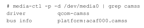
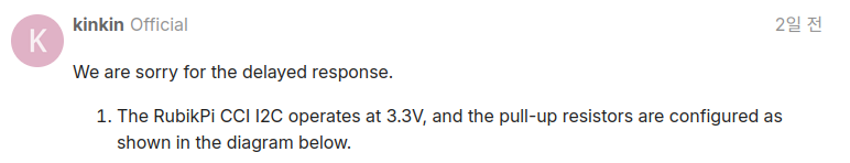
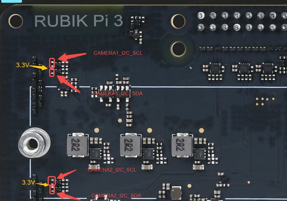
I also believe the issue is unlikely to be hardware-related. However, could you please confirm whether the CCI I2C on the RubikPi operates at 1.8V? Additionally, it seems there is a device tree mismatch. Upon investigation, I noticed that qcm6490-addons-idp.dts is currently being used. Based on our setup, one of the qcs variants may be more appropriate—could you kindly advise which of the following should be used?

vsdall@vsdall-LOQ-15IRX9:~/work/rubik_pi3/kernel/arch/arm64/boot/dts/qcom$ ls qcs6490*
qcs6490-addons-rb3gen2-hsp.dts
qcs6490-addons-rb3gen2-ia-mezz.dts
qcs6490-addons-rb3gen2-ptz-mezz.dts
qcs6490-addons-rb3gen2-video-mezz.dts
qcs6490-addons-rb3gen2-vision-mezz-hsp.dts
qcs6490-addons-rb3gen2-vision-mezz.dts
qcs6490-addons-rb3gen2.dts
qcs6490-addons-rb3gen2.dtsi
qcs6490-rb3gen2.dts

Regarding your question about the necessity of using V4L2:

Our company designs image sensors, and although Qualcomm’s built-in ISP is technically available, the cost of support makes it impractical for us. As a result, we are limited to receiving raw bayer data without any ISP post-processing, which leads to issues such as dark image corners and color inaccuracies. To resolve this, we have integrated our own ISP with the sensor, which supports MIPI continuous mode—hence my earlier question on that support.

Furthermore, there are many existing camera modules on the market that already combine sensors with ISP, often implemented via FPGA, with outputs that are not always MIPI. As you may know, MIPI and LVDS interfaces have limitations in cable length, making them unsuitable for long-distance transmission. On the other hand, while Ethernet can support long-distance connections, it generally requires lossy compression even for resolutions like Full HD at 30fps to ensure reliable transmission. This is why analog interfaces such as AHD, TVI, and CVI are often used in such scenarios.

We provide a bridge chip(ASIC) that converts analog video (NTSC, PAL, AHD, TVI, CVI) into MIPI, and this is a frequent topic(not related to us) among Raspberry Pi users. Typical issues such as “the board doesn’t receive NTSC input properly” are usually due to mismatches in formats like RGB24, RGB565, or YUV422.

In cases where the input video has already been color converted through an external ISP, we would like to ask:
Is V4L2 strictly required for handling the camera interface?
Or is there a feasible way to write a driver or process video at the application layer, directly displaying or saving frames without V4L2?

I am aware of tools like yavta, but I am not sure whether yavta works independently or still depends on V4L2 APIs under the hood. This uncertainty is one of the reasons we default to using V4L2.

Lastly, our company is working with partners on an AI-based data acquisition and analysis platform that requires input from at least five cameras, with OpenGL and OpenCL support for real-time parallel processing. Among several platforms, RubikPi is the best solution for its balanced combination of CPU, NPU, and 3D acceleration.

The camera modules for this project deliver pre-processed ISP output, which the RubikPi must receive. Unfortunately, as of now, we haven’t been able to get even a single camera stream working, let alone five. :loudly_crying_face::loudly_crying_face::loudly_crying_face::loudly_crying_face::loudly_crying_face::loudly_crying_face::loudly_crying_face::loudly_crying_face::loudly_crying_face::loudly_crying_face::loudly_crying_face::loudly_crying_face::loudly_crying_face:

If RubikPi is to be adopted more widely in smaller-scale video processing projects, like those often addressed by the Raspberry Pi, I strongly believe it will be essential to provide a path for receiving and processing camera input without relying on the internal Qualcomm ISP.

I apologize if this message was overly detailed or if I’ve overstepped in any way. Thank you very much for your time and consideration.

We are sorry for the delayed response.

  1. The RubikPi CCI I2C operates at 3.3V, and the pull-up resistors are configured as shown in the diagram below.

  2. If there is no output from the CSI, you may consider debugging from these two aspects:

  • The power on sequence of the camera

  • The init code.

  1. According to Qualcomm documentation, CAMSS should be able to meet your requirements, which is to open the camera via a V4L2 node without processing through Qualcomm’s ISP.

  2. Additionally, our company is about to develop V4L2, and you can look out for further information.

It seems that the diagram was accidentally omitted. And ould you please check whether the device tree files relating to the QCM6490~~.dts or .dtsi are correct to Rubik PI board? Because Rubik PI board does not have QCM chipset.

We’d like to inform you that the power-on sequence and initialization code have already been verified, as we’re using the same image sensor board that has been tested on Raspberry Pi 4 and 5. However, since I2C communication is not working, we’re stuck at the very first step where we need to send the initial registers.

You mentioned that your company is planning to develop V4L2 support. Can we assume that, as of now, Thundercomm has not yet successfully captured video via V4L2?

The .dts or .dtsi device tree files related to QCM6490 are applicable to the Rubik PI.
As of now, Rubik Pi captures video without utilizing V4L2.
Our technical team is soon planning to develop V4L2 support, and you can stay updated for further information.

You mentioned that the I²C diagram is as shown above, but I cannot find the diagram anywhere. Could you please confirm this part?

We sincerely apologize for any confusion caused.
The image has been successfully re-uploaded for your review.